Understanding how physical networks and virtual networks
come together to provide an end-to-end solution is critical to running
a stable production environment. The physical and virtual networks
interact with each other to provide different functionality. There
are some additional layers with the introduction of overlay networks
such as VMware NSX. This topic explains the following concepts:
VMware vSphere Architecture
The VMware vSphere architecture is very simple. There are two
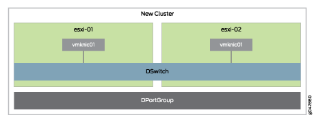
ESXi hosts in a cluster called “New Cluster.” Both of
the hosts have a distributed virtual switch called “DSwitch”
with a single port group “DPortGroup” as shown in Figure 1. The cluster is assigned to a data center
called “Datacenter.”
All NSX appliance VMs are placed into the distributed virtual
switch “DSwitch.” The local vSwitch0 is no longer used
for any type of traffic; all underlay traffic will ingress and egress
the distributed virtual switch.
VMware NSX
To enable SDN, there are many functions from management to packet
forwarding that need to be performed. Each functional component is
described next.
VMware NSX Manager
The VMware NSX Manager provides integration with VMware vCenter
Server which allows you to manage the VMware NSX environment through
VMware vCenter. All VMware NSX operations and configuration is done
through VMware vCenter, which communicates with VMware NSX Manager
through APIs to delegate tasks to the responsible owner.
VMware NSX Controller
All virtual network provisioning and MAC address learning is
handled through the VMware NSX Controller. You can think of the VMware
NSX Controller as the virtualized control plane of the SDN network.
VMware NSX Logical Distributed Router
The VMware NSX Logical Distributed Router (LDR) is responsible
for forwarding and routing all packets through the virtualized SDN
networks. It provides the following functionality:
- Default gateway for all VMs
- MAC address learning and flooding
- Bridging and routing all packets between different virtual networks
- Peers with the VMware NSX Edge to progress egress traffic outside of the virtual networks
- Virtual tunnel end-point (VTEP) termination
- Security policies and enforcement
- Multi-tenancy
The NSX LDR is a great tool for coarse or fine-grained virtual
network segmentation. Multiple VMware NSX LDRs can be created to enable
multi-tenancy or a completely separate security zone for regularity
requirements such as Payment Card Industry Data Security Standard
(PCI DSS). Each VMware NSX LDR can create virtual switches, which
are just VXLAN Network Identifiers (VNIs). You can treat virtual switches
just like you used to use VLANs in a physical network. Virtual switches
are an easy way to create multi-tiered networks for applications.
The VMware NSX LDR is split into two components: a control plane
and data plane. The control plane is responsible for the management
and provisioning of changes. The VMware NSX LDR is also installed
into each VMware ESXi host to handle the traffic forwarding and routing
as shown in Figure 2.
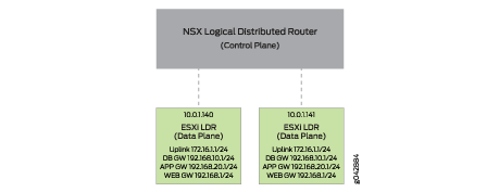
Each VMware host has a copy of the VMware NSX LDR running in
the hypervisor. All of the gateway interfaces and IP addresses are
distributed throughout the VMware cluster. This allows VMs to directly
access their default gateway at the local hypervisor. VMware NSX supports
three methods for MAC address learning:
- Unicast—Each VMware host has a TCP connection to the VMware NSX Controller for MAC address learning.
- Multicast—The physical network – in this case, the Virtual Chassis Fabric – uses multicast to replicate broadcast, unknown unicast, and multicast traffic between all VMware hosts participating in the same VNI.
- Hybrid—Each VMware host has a TCP connection to the VMware NSX Controller for MAC address learning, but uses the physical network for local process of broadcast, unknown unicast, and multicast traffic for performance.
If your environment is 100 percent virtualized, we recommend
that you use either unicast or hybrid mode. If you need to integrate
physical servers – such as mainframes – into the VMware
NSX virtual environment, you need to use multicast mode for MAC address
learning. Virtual Chassis Fabric allows you to configure multicast
with a single IGMP command and not have to worry about designing and
maintaining multicast protocols such as PIM.
All of the VMware NSX virtual switches are associated with a
VNI. Depending on the traffic profile, the LDR can either locally
forward or route the traffic. If the destination is on another host
or outside of the virtual NSX networks, the VMware NSX LDR can route
the traffic out to the VMware NSX Edge Gateway.
Each hypervisor has a virtual tunnel end-point (VTEP) that is
responsible for encapsulating VM traffic inside of a VXLAN header
and routing the packet to a destination VTEP for further processing.
Traffic can be routed to another VTEP on a different host or the VMware
NSX Edge Gateway to access the physical network.
In Table 1, you
can see all of the possible traffic patterns and how the VMware NSX
LDR handles them.
Table 1: Traffic Patterns
Handled by VMWare LDR
Source
|
Destination
|
Action
|
|---|---|---|
Local VM
|
Local VM, same network
|
Locally switch traffic
|
Local VM
|
Local VM, different network
|
Locally route traffic
|
Local VM
|
Remote VM, same network
|
Encapsulate traffic with VXLAN header and route to destination
VTEP
|
Local VM
|
Remote VM, different network
|
Encapsulate traffic with VXLAN header and route to destination
VTEP
|
Local VM
|
Internet
|
Encapsulate traffic with VXLAN header and route to VMware NSX
Edge Gateway
|
Local VM
|
Physical server outside of NSX virtual networks
|
Encapsulate traffic with VXLAN header and route to VMware NSX
Edge Gateway
|
VMware NSX Edge Gateway
The VMware NSX Edge Gateway is responsible for bridging the
virtual networks with the outside world. It acts as a virtual WAN
router that is able to peer with physical networking equipment so
that all of the internal virtual networks can access the Internet,
WAN, or any other physical resources in the network. The VMware NSX
Edge Gateway can also provide centralized security policy enforcement
between the physical network and the virtualized networks.
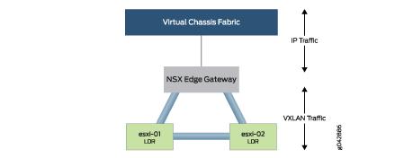
The VMware NSX Edge Gateway and LDR have a full mesh of VXLAN
tunnels as shown in Figure 3. This enables any
VMware ESXi host to communicate directly through the VXLAN tunnels
when they need to switch or route traffic. If traffic needs to enter
or exit the VMware NSX environment, the VMware NSX Edge Gateway removes
the VXLAN header and routes the traffic through its “Uplink”
interface and into the Virtual Chassis Fabric.
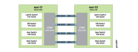
Each virtual switch on the VMware NSX LDR needs to be mapped
to a VNI and multicast group to enable the data plane and control
plane. It is as simple as choosing a different VNI and multicast group
per virtual switch as shown in Figure 4.
As VM traffic from esxi-01 needs to reach esxi-02, it simply
passes through the VXLAN tunnels. Depending on the type of traffic,
there are different actions that can take place as shown in Table 2.
Table 2: Traffic Types and Actions
Traffic Type
|
Action
|
|---|---|
Unicast
|
Route directly to the remote VTEP through the Virtual Chassis
Fabric
|
Unknown Unicast
|
Flood through multicast in the Virtual Chassis Fabric
|
Multicast
|
Flood through multicast in the Virtual Chassis Fabric
|
It is possible to associate multiple VNIs with the same multicast
group; however, in the MetaFabric Architecture 2.0 lab, we assigned
each VNI a separate multicast group for simplicity.
Overlay Architecture
The term “underlay” refers to the physical networking
equipment; in this case, it is the Virtual Chassis Fabric. The term
“overlay” refers to any virtual networks created by VMware
NSX. Virtual networks are created with a MAC-over-IP encapsulation
called VXLAN. This encapsulation allows two VMs on the same network
to talk to each other, even if the path between the VMs needs to be
routed as shown in Figure 5.
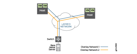
All VM-to-VM traffic is encapsulated in VXLAN and transmitted
over a routed network to the destination host. Once the destination
host receives the VXLAN encapsulated traffic, it can remove the VXLAN
header and forward the original Ethernet packet to the destination
VM. The same traffic pattern occurs when a VM talks to a bare metal
server. The exception is that the top-of-rack switch handles the VXLAN
encapsulation on behalf of the physical server, as opposed to the
hypervisor.
The advantage of VXLAN encapsulation is that it allows you to
build a network that is based on Layer 3. The most common underlay
architecture for SDN is the IP fabric. All switches communicate with
each other through a typical routing protocol such as BGP. There is
no requirement for Layer 2 protocols such as Spanning Tree Protocol
(STP).
One of the drawbacks to building an IP fabric is that it requires
more network administration. Each switch needs to be managed separately.
Another drawback is that to allow the integration of bare metal servers
with VMware NSX for vSphere, multicast is required for the integration
of VXLAN and MAC address learning. This means that in addition to
building an IP fabric with BGP, you also need to design and manage
a multicast infrastructure with Protocol Independent Multicast (PIM)
protocols.
The advantage of Virtual Chassis Fabric is that you can build
an IP fabric and multicast infrastructure without having to worry
about BGP and PIM. Because the Virtual Chassis Fabric behaves like
a single, logical switch, you simply create integrated routing and
bridging (IRB) interfaces and all traffic is automatically routed
between all networks because each network appears as a directly connected
network. To enable multicast on a Virtual Chassis Fabric, you simply
enable Internet Group Management Protocol (IGMP) on any interfaces
requiring multicast. There is no need to design and configure PIM
or any other multicast protocols.
No comments:
Post a Comment